Download Images Library Photos and Pictures. Capacitor Start Motors Diagram Explanation Of How A Capacitor Is Used To Start A Single Phase Motor Bright Hub Engineering Equivalent Circuit Of A Single Phase Induction Motor Circuit Globe Hmsc September 2001 Newsletter Single Phase Induction Motors Electric Motor
Single phase motors are inherently noisier and less smooth running than polyphase motors. Terminal connections for capacitor start single phase motors.

. Manuals Wiring Diagram Induction Motor Single Phase Full Version Hd Quality Single Phase Manualguidebookscom Prevato It Single Phase Induction Motors Ac Motors Electronics Textbook Single Phase Induction Motor The Engineering Knowledge
Facebook It is evident from the phasor diagram that the current through the starter winding is leads the voltage v by.
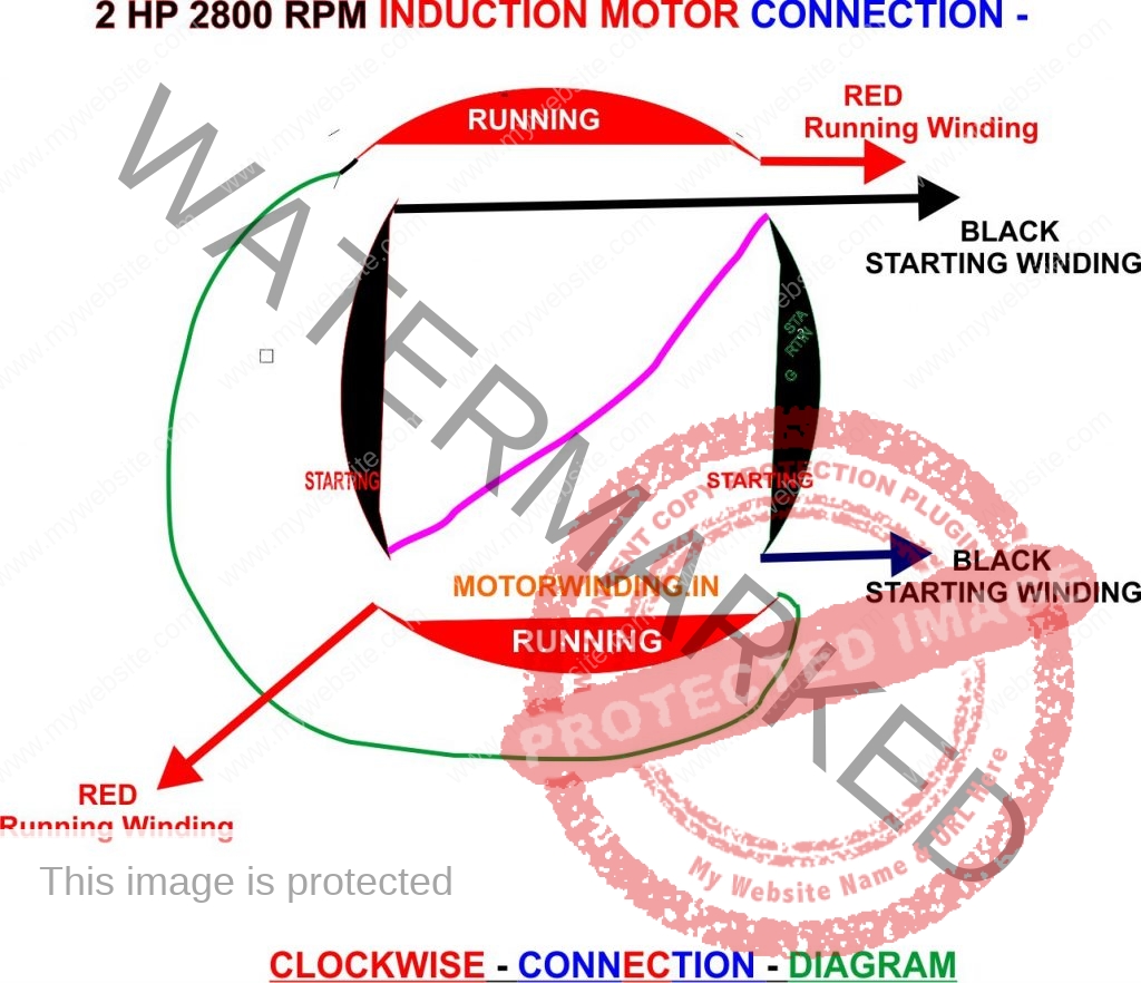
. The wires in the mains lead of this machine are coloured in accordance with. Suited to a variety of applications this totally enclosed fan cooled v motor is continuously rated for reliable long. Thank you for purchasing this clarke product.
According to earlier the lines in a single phase motor wiring diagram with capacitor represents wires. Diagram dd6 diagram dd7 m 1 ln e diagram dd8 ln e l1 l2 l3 sc z1 u2 z2 u1 cap. The blue wire is connected directly to the neutral wire coming from the main power supply coming from the back and the red wire and black wire are connected to a capacitor.
Occasionally the wires will cross. Wiring diagram single phase motors 1empc permanent capacitor motors 1empcc capacitor start capacitor run motors electric motors limited when a change of direction of rotation is required and a change over switch is to be used it will be necessary to reconnect the termination on the terminal block. Thus a capacitor start induction run motor produces a better rotating magnetic field than the split phase motors.
Injunction of two wires is usually indicated by black dot in the intersection of two lines. To allow important single phase machines only. Clarke single phase induction motor wiring diagram.
This type of motor is designed to provide strong starting torque and strong running for applications such as large water pumps. The black wire is tightly connected to the capacitor and the same is connected with the second wire of the capacitor to the red wire coming from the running winding along with the wire facing the power supply coming from the back. Cooling to compressor pump and electric motor.
However it does not imply link between the cables. Thermal contacts tb white m 1 z2 yellow z1 blue u2 black u1 red bridge l1 and l2 if speed controller sc is not required m 1 ln e white brown blue l1 l2 n sc bridge l1 and l2 if speed controller sc is not. Text links below go to applicable products on amazon and ebay.
At the bottom of this post is also a video about dc shunt motors. Frequent stopstarts andor. Motor rotation terminal connections single voltage.
Because there is a backward rotating component of flux there are pulsating torques so the torque speed curve is really just a representation of the average torque. The reconnection must be carried out by qualified electrician. Capacitor start capacitor run induction motors are single phase induction motors that have a capacitor in the start winding and in the run winding as shown in figure 12 and 13 wiring diagram.
It is important to point out from the phasor diagram that the phase difference between im and is is almost 80 degrees as against 30 degrees in a split phase induction motor. Capacitor start induction motor csim circuit wiring diagram and torque speed curve. For all other single phase wiring diagrams refer to the manufacturers data on the motor.
I have compiled a group of single phase electric motor wiring diagrams and terminal connections below.
Https Encrypted Tbn0 Gstatic Com Images Q Tbn And9gctrthclzzqovltpt Z3xmfcfhsomc Djbxni172pn0rprmvzh0c Usqp Cau
Diagram Wiring Diagram For Single Phase Ac Motor Full Version Hd Quality Ac Motor Chakradiagram Patinage Angers Fr
 Manuals 1 Phase Induction Motor Wiring Diagram Pdf Full Version Hd Quality Wiring Diagram Pdf Jeepmanualguidecom Prevato It
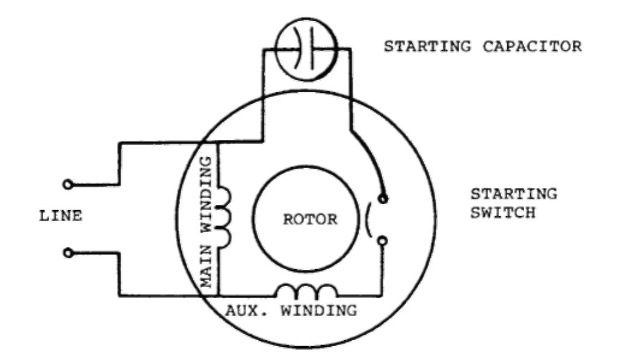 Single Phase Induction Motors Electric Motor
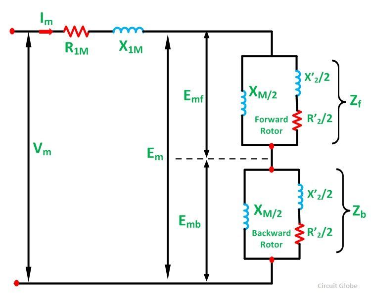 Equivalent Circuit Of A Single Phase Induction Motor Circuit Globe
Wiring Wiring Diagram Of Single Phase Ac Motor Full Hd Version Dominostables Kinggo Fr
 Diagram 240v Motor Wiring Diagram Single Phase Wiring Diagram Full Version Hd Quality Wiring Diagram Diagramasinfol Robertaalteri It
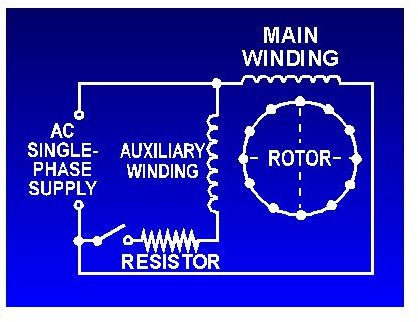 Capacitor Start Motors Diagram Explanation Of How A Capacitor Is Used To Start A Single Phase Motor Bright Hub Engineering
 Connection Diagram For 1 Phase Electric Motor Single Phase Asynchronous Motor Wiring And Starting Diagram
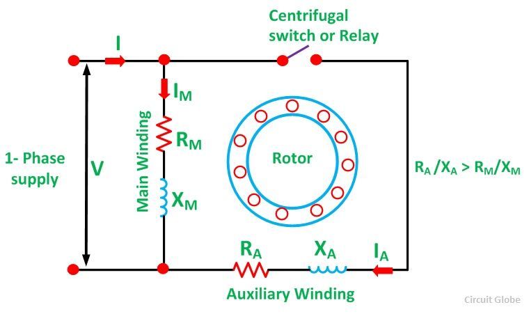 What Is A Split Phase Induction Motor Its Applications Circuit Globe
Getting The Motor Started Single Phase Motor Winding Connection
 Diagram In Pictures Database Ge Induction Motor Wiring Diagram Just Download Or Read Wiring Diagram Jije Kripke Models Onyxum Com
Hmsc September 2001 Newsletter
 Kbreee Equivalent Circuit Of Single Phase Induction Motor
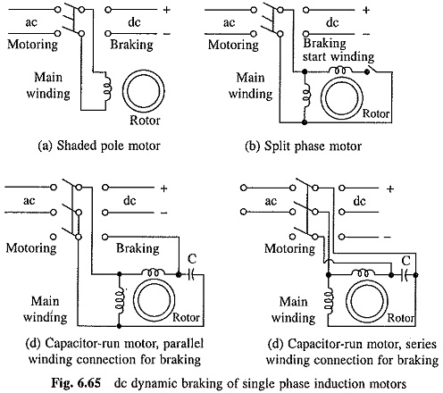 Braking Of Single Phase Induction Motor Plugging And Reversal
 Diagram 110 Single Phase Motor Wiring Diagrams Full Version Hd Quality Wiring Diagrams Df1x44 Epaviste Gratuit Idf Fr
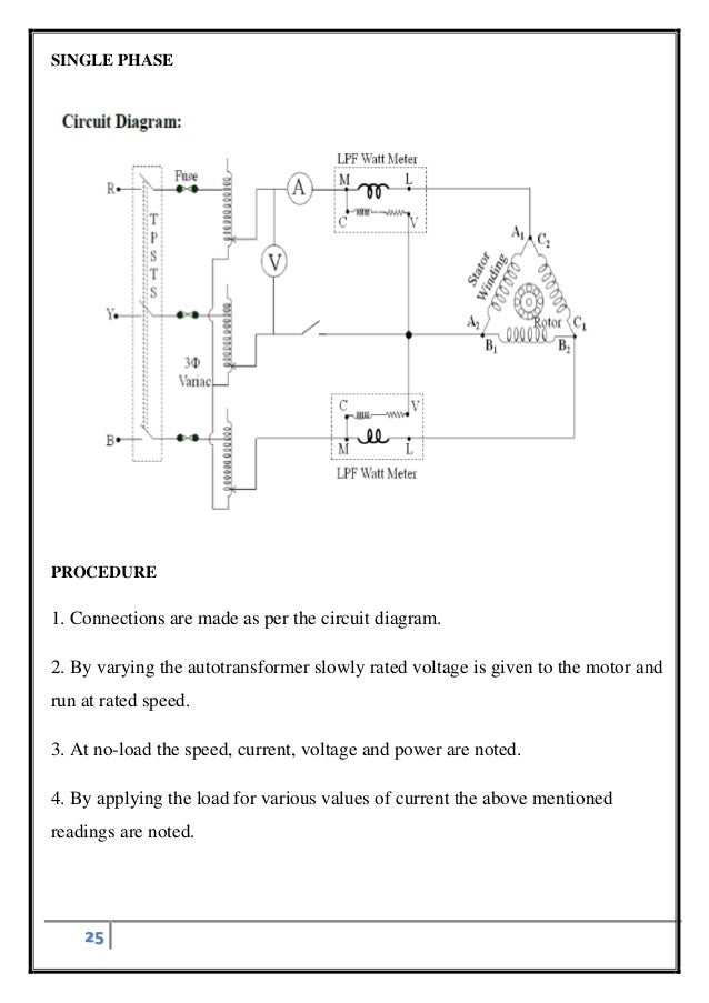 Diagram 3 Phase Motor Wiring Diagram Single Phase Ac To One Line Full Version Hd Quality One Line Wiringyourmindforhealth Cometacomunicazioni It
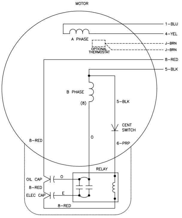 Vfds For Single Phase Applications Keb
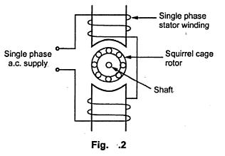 Construction Of Single Phase Induction Motor Electrical Engineering Interview Questions
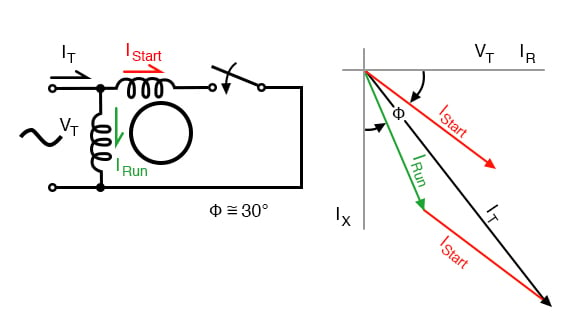 Single Phase Induction Motors Ac Motors Electronics Textbook
 Single Phase Induction Motor Winding Diagram Electrical Diagram Electrical Circuit Diagram Capacitors
 Types Of Single Phase Induction Motors Javatpoint
Diagram Single Phase Capacitor Start Induction Motor Wiring Diagram Full Version Hd Quality Wiring Diagram Tapandbwiring Ritamorlando It
 Diagram 240v Motor Wiring Diagram Single Phase Collection Wiring Diagram Full Version Hd Quality Wiring Diagram Wolfewiring Kyosho Center Eu


Tidak ada komentar:
Posting Komentar